The idea
Every equilibrium and dynamics problem puts the weight at the centre of mass. For a uniform rod that’s obviously the middle, but for a bracket, a robot chassis or a gripper finger you have to work it out.
The idea comes straight from the parallel force system in Forces and moments: the moment of the whole object’s weight about a point equals the sum of the moments of all its parts about that point.
For a flat plate of uniform thickness and density, the weight of each part is proportional to its area, so you can use areas directly. The same works for with the values.
Composite shapes
Split the shape into simple pieces whose centroids you know:
| Shape | Centroid |
|---|---|
| Rectangle | The middle |
| Triangle | of the height up from the base |
| Circle or semicircle | Centre; a semicircle’s is from the flat edge |
Then tabulate area × position and divide. Holes count as negative area.
Worked example: an L-shaped bracket
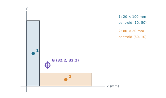
The bracket is a 20 × 100 mm upright with an 80 × 20 mm foot attached at the bottom right. Find its centre of mass from the bottom-left corner.
Answer
Part A (mm²) 1 upright 2000 10 50 20 000 100 000 2 foot 1600 60 10 96 000 16 000 Total 3600 116 000 116 000 32.2 mm · 32.2 mm G sits in the empty corner of the L, outside the material. That’s normal for hollow or bent shapes.
Curved shapes: integrate with strips
When the edge is a curve , slice the shape into thin vertical strips of width :
- Whole shape: area , and its moment is .
- One strip at distance x: area , moment .
- Equate the whole shape’s moment with the total of all the strips:
For , each vertical strip’s own centroid is halfway up it, at , which is where the comes from. (Equivalently, use horizontal strips of width : .)
Worked example: under a parabola
Find the centroid of the region under from to .
Answer
→ 1.5 → 1.2 Sense check: the shape is fatter on the right, so is past the halfway point (1), and it’s flat along the bottom, so is low.
Why it matters for robots
- Tipping: a mobile robot tips over when its centre of mass moves outside the wheelbase, for example when an arm reaches out or it climbs a slope. Keeping G low and central keeps it stable.
- Motor torque: an arm joint has to hold the load’s weight at the distance to its centre of mass, . Moving the motor close to the base reduces that d for the joints above it.
- Inertia: a uniform slender rod’s moment of inertia about its centre, , assumes the mass is spread evenly with G at the middle. Real links with holes, bosses and fittings have their G elsewhere.
Common mistakes
- Adding a hole instead of subtracting it.
- Measuring every from a different origin. Pick one corner and stick to it.
- Forgetting the ½ in the integral.
- Assuming G must be on the material. It doesn’t have to be.
Check yourself
1. A 100 × 60 mm plate has a 20 mm diameter hole centred at (70, 30) mm. Find .
Plate: 6000 mm² at x = 50. Hole: mm² at x = 70. 48.9 mm. The hole pulls G slightly left, away from it. mm by symmetry.
2. A right-angled triangle has a 90 mm base along the x-axis and a 60 mm height up the y-axis. Where's its centroid?
One third along each leg from the right angle: (30, 20) mm.
Back to WM1AC, or practise in WM1AC practice questions.