The idea
A diode is a one-way valve for current. In the symbol, current can only flow the way the triangle points, and getting through costs a small, roughly fixed voltage, the forward voltage V. Backwards, it blocks, up to its limit .
One diode on its own (a half-wave rectifier) lets the positive half of the AC through and throws the negative half away. A full bridge uses four diodes arranged in a diamond so that both halves come out positive.
How the bridge works
Name the four corners: A and B connect to the AC, + and − connect to the load.
| Diode | Allows current |
|---|---|
| D1 | A → + |
| D2 | B → + |
| D3 | − → A |
| D4 | − → B |
Two arrows point into +, two point out of −. So whatever the AC does, current can only arrive at + and leave from −. It always goes through the load from + to −.
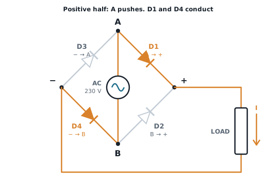
Positive half (A pushes): A → D1 → + → load → − → D4 → B. D2 and D3 would need current to flow against their arrows, so they block.
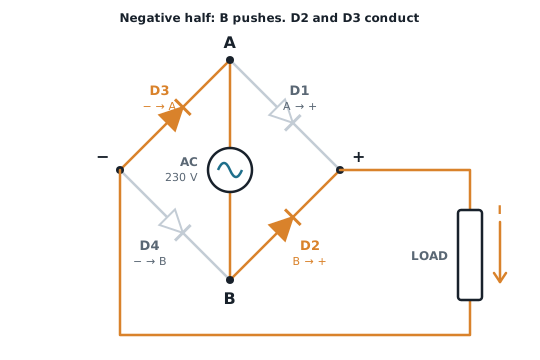
Negative half (B pushes): B → D2 → + → load → − → D3 → A. Same direction through the load.
The two things to remember
- Current always passes through exactly two diodes. So the output peak is , and two diodes are always making heat.
- The output is a row of positive humps, two per AC cycle: 100 per second at 50 Hz.
A three-phase bridge (6 diodes) on a three-phase supply gives six overlapping humps per cycle, which is nearly flat DC. That’s what big industrial kit uses.
Smoothing with a capacitor
The humps still drop to 0 V between peaks. A capacitor across the output works like a water tank: it fills at each peak, and the load drains it a little until the next hump refills it. The dip is the ripple, .
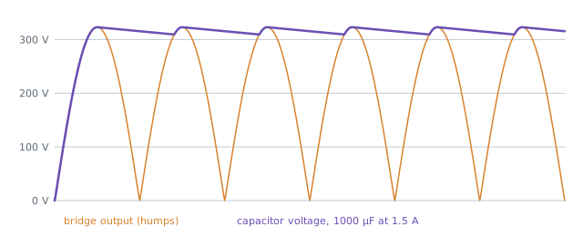
Deriving the ripple:
- Refills happen 100 times a second, so the gap is ms.
- In that gap the load takes charge (current is charge per second).
- For a capacitor , so the voltage drops by .
The capacitor charges to the top of each hump, minus the two diode drops:
Heat in the bridge
- Power = voltage × current. A conducting diode has a fixed across it, so at every instant.
- Averaged over time, is constant, so . Diodes use average current, unlike resistors and MOSFETs, which use with RMS.
- Two diodes are always on, so .
- You’re usually given RMS, and for these humps (see AC values).
Choosing a bridge from its datasheet
| Check | Rule | Why |
|---|---|---|
| Above your current, with margin (~50%) | It sets how much average current it can carry without overheating | |
| Above the peak, 325 V on UK mains, with margin | When a diode is off, it has to block the full peak | |
| Lower is better | Less heat, slightly higher output |
Worked example
A robot charger uses a GBPC12 bridge ( V, A, V) on 230 V mains. It draws 2 A RMS and has a 4700 µF smoothing capacitor. Find the bridge’s heat, the capacitor’s peak voltage and the ripple. Is the bridge suitable?
Answer
W V V Suitable: 12 A ≫ 2 A, and 800 V > 325 V.
Common mistakes
- Forgetting the two diode drops: it’s , not .
- Forgetting µF is . 4700 µF = 0.0047 F.
- Using 50 instead of in the ripple formula. A full bridge refills twice per cycle.
- Checking against 230 V instead of the 325 V peak.
Check yourself
1. In the positive half, why doesn't current go A → D3?
D3 only allows − → A. Going A → − would be against its arrow, so it blocks.
2. You double C. What happens to the ripple?
It halves, because .
3. A bridge with V carries 3 A RMS. How much heat does it make?
W.