The idea
The last link in the chain is a set of switches arranged so the motor gets the right voltage, polarity and timing. PWM sets the speed. The arrangement of switches sets the direction, and for brushless motors, which coil is energised.
Brushed DC: the H-bridge
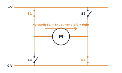
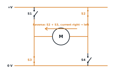
One MOSFET with PWM (a single-switch chopper) controls speed, but only in one direction. To reverse the motor you need to flip the polarity across it. Four switches in an H do that:
| Switches on | Result |
|---|---|
| S1 + S4 | Forward: current left → right through the motor |
| S2 + S3 | Reverse: current right → left |
| S3 + S4 | Brake: the motor’s terminals are shorted, so its own back-EMF slows it fast |
| S1 + S3 or S2 + S4 | Never. This connects +V straight to 0 V through two switches (shoot-through), which destroys them. Drivers add dead time to prevent it |
The driver must also carry the motor’s continuous current, and should limit it so a stalled motor doesn’t overheat.
Brushless (BLDC, PMSM): the three-phase inverter
Three half-bridges, one per motor phase (U, V, W), six switches in total. Switching them in sequence makes a rotating magnetic field that drags the magnet rotor round. With no brushes, there’s less wear and higher efficiency.
- is the power factor, typically 0.92–1. is the efficiency, typically 90–95%.
- The last formula has a because each transistor carries its phase’s current only half the time, and RMS scales with the square root of the on-time (). That is what goes into the MOSFET power loss calculation.
Worked example
A 500 W brushless motor runs from a 48 V battery, with and . Find the phase current and the current through each transistor.
Answer
V A A per transistor
Stepper motors
| Type | Coils | Driver |
|---|---|---|
| Bipolar | Two separate coils | Two H-bridges, to reverse the current in each coil |
| Unipolar | Centre-tapped coils | Simple low-side switches that pull each half-coil to ground in turn |
Both use PWM current chopping: the driver measures the coil current and switches off the instant it reaches the rated limit.
Check yourself
1. Which pair of switches in an H-bridge must never be on together, and why?
Two on the same side (S1 + S3, or S2 + S4). They short the supply to ground.
2. How many H-bridges does a bipolar stepper need?
Two, one per coil.